| DUCT PROTECTION – 16416 Nozzle – 1 F-Point | |||
| Duct Only | Transitional Duct Coverage | Large Ducts – Perimeter up to 2100 | Large Ducts – Perimeter up to 2500(11983) |
| Unlimited Changes in Direction – Unlimited Length Max. Diagonal Dimension = 470mm Placed 50mm to 200mm in Duct aimed straight down middle of duct 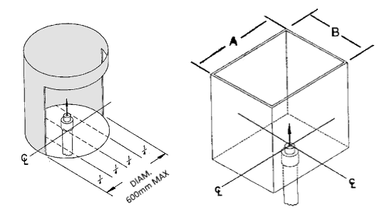 |
Size protection in accordance with the size of the cross section of the transition at the level where the tip of the nozzle is in the transition. The nozzles are to point straight up into the transition area.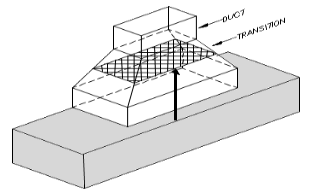 |
Duct with 1275mm to 2100mm Perimeter Divide Duct into Imaginary Smaller Ducts Equal to or Less Than 1250mm in Perimeter. Each Imaginary Duct Section Will Require a PN 16416 Nozzles as Shown. 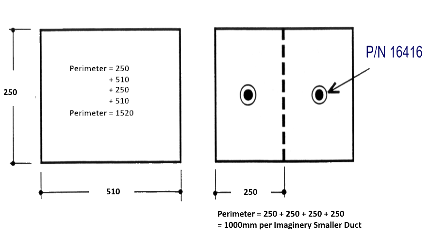 |
Duct to 2500mm Perimeter Unlimited Length – Unlimited Changes in Direction Max. Diagonal Dim.= 930mm 2 x 11983 Nozzles Total of 3 F-Points Placed 50mm to 200mm in Duct aimed straight down middle of duct 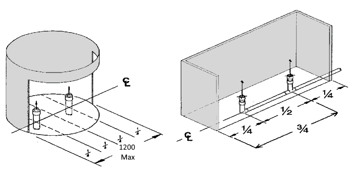 |
| PLENUM PROTECTION – 11982 Nozzle – 1 F-Point | ||
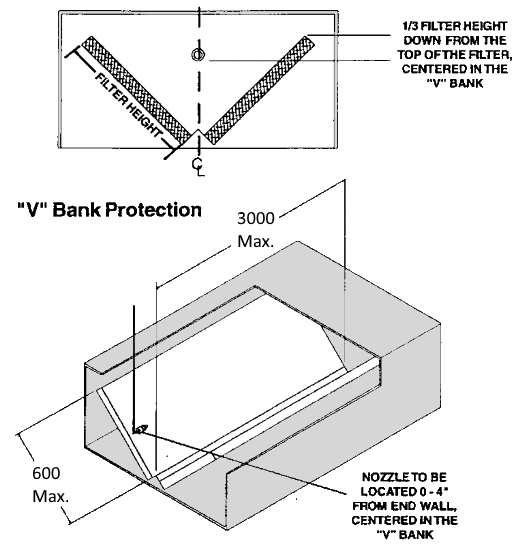
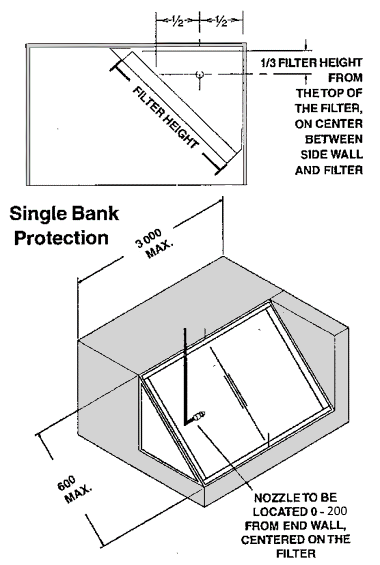
| 1 x 11982 Nozzle Will Protect a Single or “V” Bank Filter Plenum of 1200 wide X 3000mm long.
A 11982 Nozzle Is Required for Every 3000mm of Plenum Length and Every 1200mm of Plenum Width. Nozzle Placement Can Be End to End, or in a Row |
 |
| APPLIANCES | ||||||
| Appliances come in many shapes and Sizes and these are new products are constantly developing. When designing and maintaining a system it is IMPORTANT to reveiw the appliances that are being protected and ensure that the system will perform as designed. | ||||||
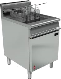 Fryers |
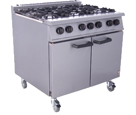 Range |
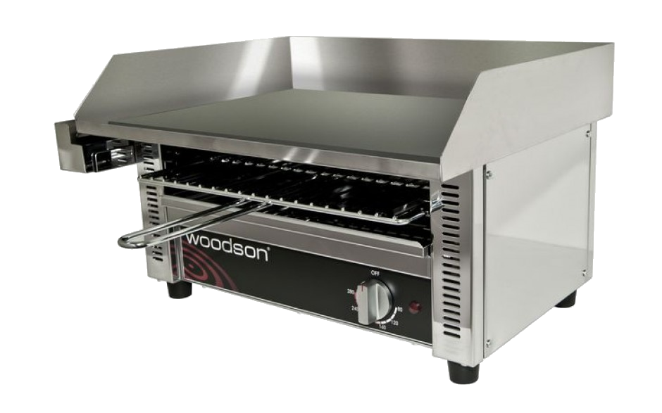 Griddle |
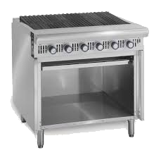 Broiler |
 Wok |
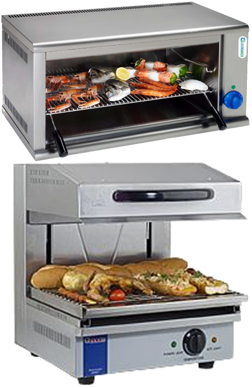 Salamander / Cheese Melter |
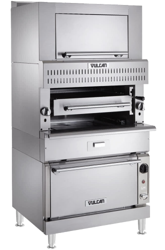 Upright Broiler |
| FRYER PROTECTION Note: Maximum & minimum heights must be measured vertically from the tip of nozzle to the top of the appliance. |
||||
| Full Vat Fryer 1 x 13729 Nozzle – 2 F-Points |
Full Vat Fryer – LOW PROXIMITY 2 x 11982 Nozzles – 1 F-Point |
Full Vat Fryer – 1” DRIP BOARD 1 x 13729 Nozzle – 2 F-Points |
Split Vat Fryer 1 x 13729 Nozzle – 2 F-Points |
Fryers Exceeding Single Nozzle Coverage |
| MAX SIZE: 500 x 650mm Incl drainboard (500 x 480mm Excl. drainboard) Nozzle Height: Max 1220mm – Min 920mm The nozzle is located along or anywhere within the protected area and aimed to the center of the hazard area of the appliance. 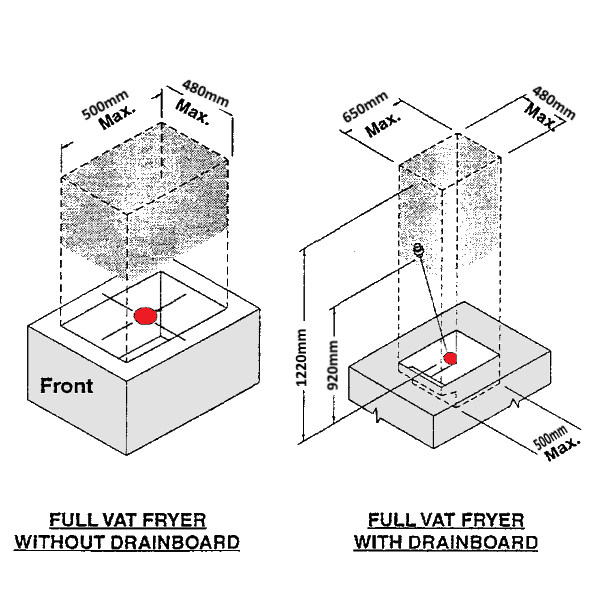 |
MAX SIZE: 500 X 650mm Incl. drainboard (500 x 480mm Excl. drainboard) Nozzle Height: Max 920mm – Min 450mm The nozzles is located on the perimeter of the appliance, 15mm back from the inside edge of the appliance and within a zone extending 150mm in both directions of the center of the hazard. The nozzles are to be located 180° apart. They are to be aimed at a point 80mm below the top of the appliance and directly below the opposing nozzle. 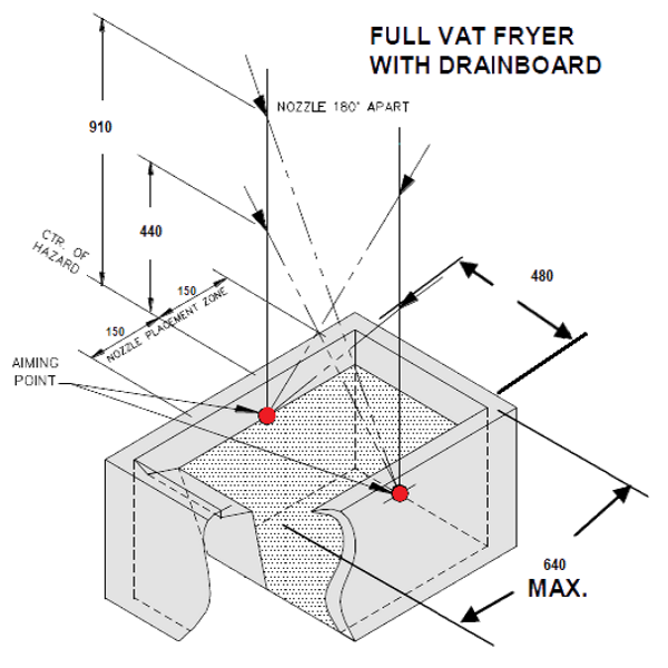 |
MAX AREA: 4026 sq.cm) of FRY POT Nozzle Height: Max 1250mm – Min 920mm The nozzle must be located anywhere over the protected area and aimed at the center of the hazard. Figure 1 has a cooking area is 8052 sq.cm. Dividing the area by the listed area of 4025 and the rounded up result is 2. Therefore, two nozzles are required to protect this appliance. Figure 2 shows how the hazard was divided into two equal modules 660 x 610mm and each module has an area of 4026 sq.cm. When protecting a tilting skillet with a cover or lid the nozzles must be placed to the front edge of the appliance and aimed to the center of the module. This process can apply to larger fryer up to maximum fryer size of 5570 sq.cm. 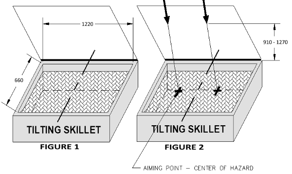 |
MAXIMUM AREA: 360 X 530mm Incl. drainboard (360 x 380mm Excl. drainboard) Nozzle Height: Max 1270mm – Min 1020mm The nozzle must be located within the protected area on a line perpendicular to the longest side of the fryer passing through the center of the hazard area. Nozzle to be aimed to the center of the hazard area of the appliance. 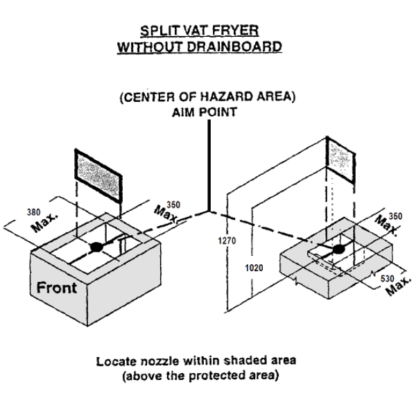 |
Multiple fryer nozzles may be used to protect single vat fryers up to a maximum protected area of 5570 cm2. The fryer must be divided into modules for single nozzle coverages and the nozzle located and aimed for each module as indicated.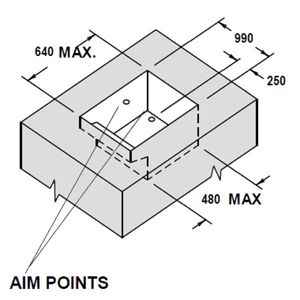 |
| RANGE PROTECTION Note: Maximum & minimum heights must be measured vertically from the tip of nozzle to the top of the appliance. |
||||
| Single Burner Range 1 x 11984 Nozzle – ½ F-Point |
Single Burner Range – Overhead 1 x 11984 Nozzle – ½ F-Point |
Two Burner Range 1 x 11982 Nozzle – 1 F-Point |
RANGE PROTECTION 1 x 11982 Nozzle – 1 F-Point |
4 Burner Range 1 x 14178 Nozzle – 2 F-Point |
| 450 x 450mm Cooking Area (Single Burner) Nozzle Height: Max 1050mm – Min 600mm Nozzle Placement directly over Burner Center 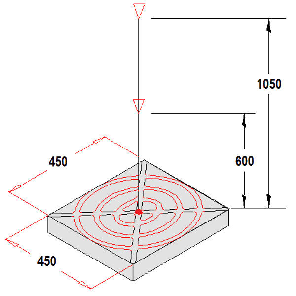 |
450 x 450mm Cooking Area (Single Burner) Nozzle Height: Max 600mm – Min 500mm Nozzle on perimeter of burner aimed at a point 170mm above the center 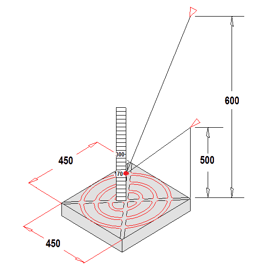 |
350 x 700mm Cooking Area (2 Burner) Nozzle Height: Max 1200mm – Min 1100mm Nozzle Placement directly over Appliance Center 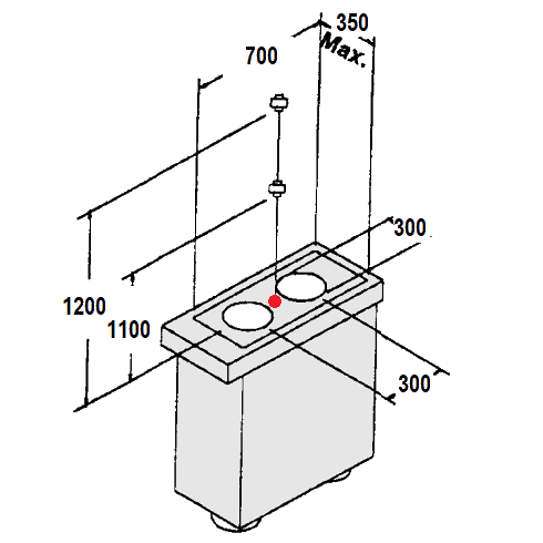 |
300 x 600mm Cooking Area (2 Burner) Nozzle Height: Max 1250mm – Min 900mm Nozzle Placement directly over Appliance Center 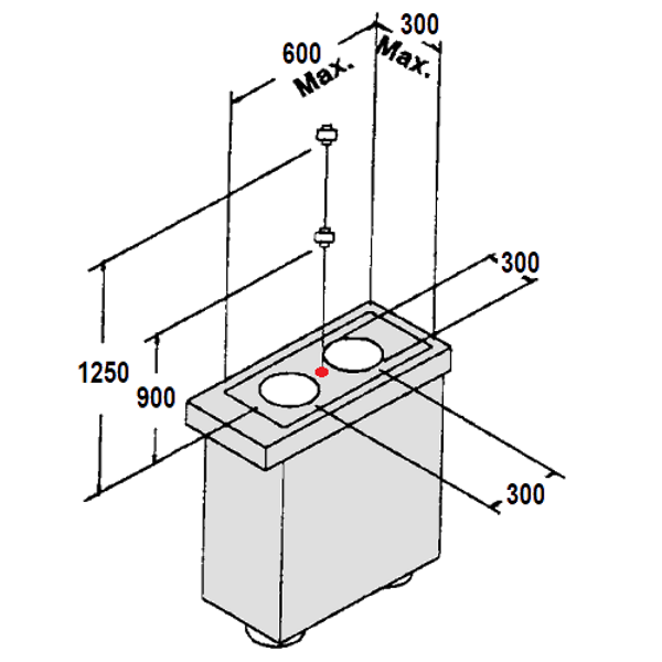 |
600 x 600 Cooking Area (4 Burner) Nozzle Height: Max 1250mm – Min 450mm Nozzle Placement directly over Appliance Center 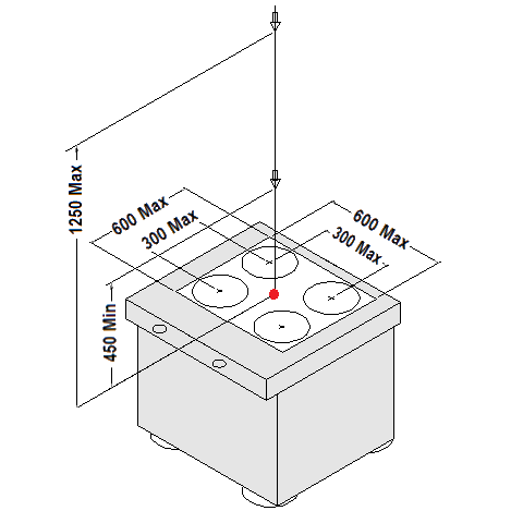 |
| GRIDDLE PROTECTION Note: Maximum & minimum heights must be measured vertically from the tip of nozzle to the top of the appliance. |
||||
| Griddle Perimeter 1 x 11982 Nozzle – 1 F-Point |
Griddle Perimeter 1 x 14178 Nozzle – 2 F-Point |
Griddle Perimeter – Low Proximity 1 x 14178 Nozzle – 2 F-Point |
Griddle Overhead 1 x 13729 Nozzle – 2 F-Point |
Griddle Perimeter Multiple Nozzles |
| Cooking Area : 900 x 750mm Nozzle Height: Max 1200mm – Min 750mm Nozzle Located on Appliance Perimeter and Aimed at the Point where a straight line intersect with an 270mm square place about the center of the griddle. 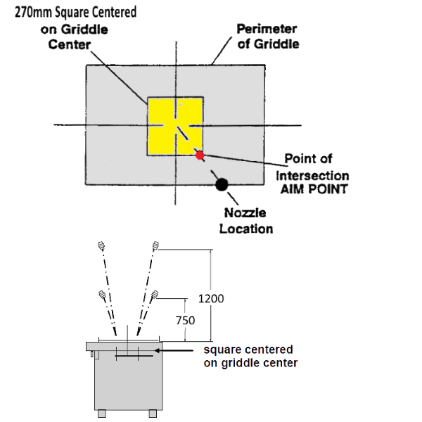 |
Cooking Area : 1200 x 750mm Nozzle Height: Max 1250mm – Min 600mm Nozzle Located on Appliance Perimeter and aimed at the point where a straight line intersect with an 270mm square place about the center of the griddle. 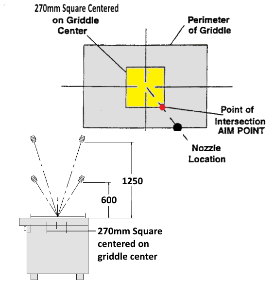 |
Cooking Area : 1200 x 750mm Nozzle Height: Max 600mm – Min 375mm Nozzle Located on Appliance Corners and Aimed at the Point where a straight line intersect with an 270 square place about the center of the griddle. 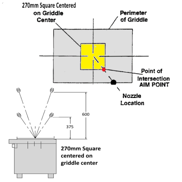 |
Cooking Area : 1050 x 750mm Nozzle Height: Max 1250mm – Min 950mm Nozzle Located over the center of the Appliance, anywhere within a 300mm square and aimed straight down. 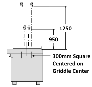 |
Protection of appliances larger than the listed appliance size is accomplished by dividing it into modules equal to or smaller than the listed size. Each module is then protected as a individual appliance.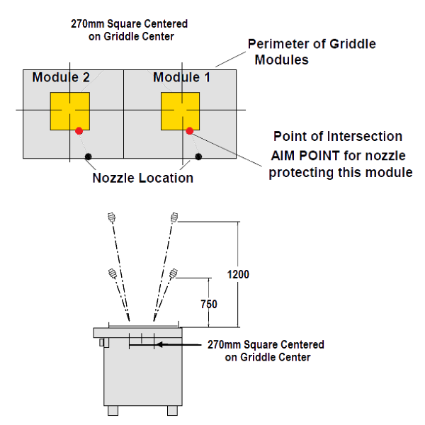 |
| APPLIANCE SPECIFIC COVERAGE Note: Maximum & minimum heights must be measured vertically from the tip of nozzle to the top of the appliance. |
||||
| Wok 1 x 11982 Nozzle – 1 F-Point |
Gas or Electric Radiant Broiler 1 x 11982 Nozzle – 1 F-Point |
Lava or Similar Rock Broiler 1 x 11983 Nozzle – 1.5 F-Point |
Upright Broiler 2 x 11984 Nozzles – ½ F-Points |
Salamanders & Cheese Melters |
| Diameter of WOK Max 600mm – Min 350mm Nozzle Height: Max 1250mm – Min 1000mm Nozzle Located Anywhere within 25mm Diameter of Center of Wok Aimed at Center of Wok 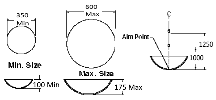 |
Cooking Area : 600 x 600mm Nozzle Height: Max 1200mm – Min 450mm Nozzle Located Over the Appliance Aimed at Midpoint of Hazard Area 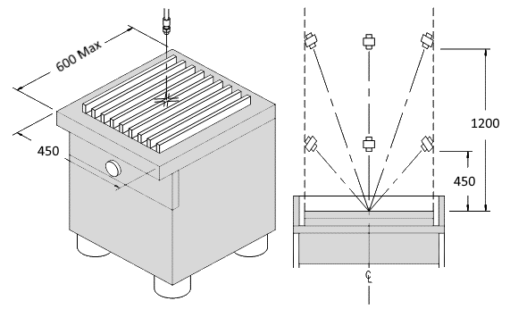 |
Cooking Area : 600 x 600mm Max 2 Layers of Rock Nozzle Height: Max 1100mm – Min 450mm Nozzle Located Over the Appliance Aimed at Midpoint of Hazard Area 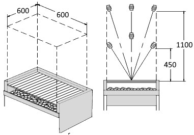 |
Size : 760 x 710mm 2 x 11984 .5fp Nozzle. Upper Nozzle in the Center of the Space Above the Grate, aimed to Opposite Corner Lower Nozzle aimed at the Center of Drip Pan Opening 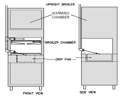 |
OPTION 1 – Up to 950mm in length – 11982 1fp Nozzle. Nozzle should be located in the middle of the opening and aimed at the rear opposite corner. OPTION 2 – Up to 950mm in length – 2 x 11984 Nozzles. Nozzles to be located on the same side of the salamander, positioned in the middle of the upper and lower opening, aimed to the rear opposite corner 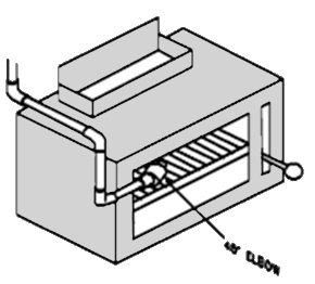 |
| ZONE DEFENSE Note: Maximum & minimum heights must be measured vertically from the tip of nozzle to the top of the appliance. |
||||
| 14178 Nozzles – 2 F-Point used. Nozzles are a maximum of 500mm apart on center and max 150mm from each end of the hood. All nozzles are in a straight line, 1150 – 1275mm above the surface of the appliances, aimed straight down. The protected rectangular area is 850mm (425mm from centerline of the nozzles) x length of the hood. ZD LIMITATIONS |
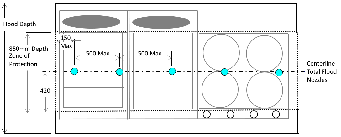 |
|||
| Appliance Type | Maximum Cooking Hazard | |||
| Fryer | 850mm deep x (0.5 M2 total) | |||
| Range | 850mm deep x Unlimited Length | |||
| Wok | maximum 650mm Diameter x 175mm Deep | |||
| Wok | minimum 350mm Diameter x 100mm Deep | |||
| Griddle | 750mm deep x Unlimited Length | |||
| Lava Rock Char-broiler | 600mm deep x Unlimited Length | |||
| Gas or Electric Radiant Char-broiler | 600 mm deep x Unlimited Length | |||
| Mesquite Charcoal (Solid Fuel) Char-broiler (6 in. Maximum Fuel Depth) | 710mm deep x Unlimited Length | |||
| Mesquite Chips & Chunks Char-broiler (6 in. Maximum Fuel Depth) | 710mm deep x Unlimited Length | |||
| Mesquite Logs Char-broiler (11 in. Maximum Fuel Depth) | 710mm deep x Unlimited Length | |||